+ Reply to Thread
Page 18 of 19 FirstFirst 1 2 3 4 5 6 7 8 9 10 11 12 13 14 15 16 17 18 19 LastLast
Results 256 to 270 of 278

Thread: Ariel #97

  1. #256
    Join Date
    Sep 2008
    Location
    Brooksville, FL
    Posts
    720
    And option #4 could be a 3" dia. patch that gets welded inside the mast. You drill a series of small say 1/4" holes around what will be the perimeter of the patch. Then you hammer the patch into a curve similar to the inside of the mast. Wedge it in place inside the mast. and start by plug welding the 1/4" holes around the perimeter. When they are welded you have a solid backing to plug weld the oblong hole and don't have to worry about blowing it out on the edges as you try to weld it up. Once it is welded and ground smooth you can drill the new hole and have extra meat in the area to help support the area and reinforce it.


    Or, you could do what I figured out in the end would have been cheaper for me after I spent all the money rehabbing my mast and buy a new one from US Spars.


    Options abound on different ways to skin that cat don't they?
    JERRY CARPENTER - C147
    A man can succeed at almost anything for which he has unlimited enthusiam.

  2. #257
    Join Date
    Sep 2012
    Location
    Philly, PA
    Posts
    179
    Quote Originally Posted by Commander 147 View Post
    Or, you could do what I figured out in the end would have been cheaper for me after I spent all the money rehabbing my mast and buy a new one from US Spars.
    AH! no. I will fix myself... actually, i have been doing a lot of aluminum and bronze welding, so I dont feel as apprehensive about welding on a 3" patch.
    A97 build images, drawings and other data:
    https://drive.google.com/drive/folde...vh?usp=sharing

  3. #258
    Join Date
    Sep 2012
    Location
    Philly, PA
    Posts
    179
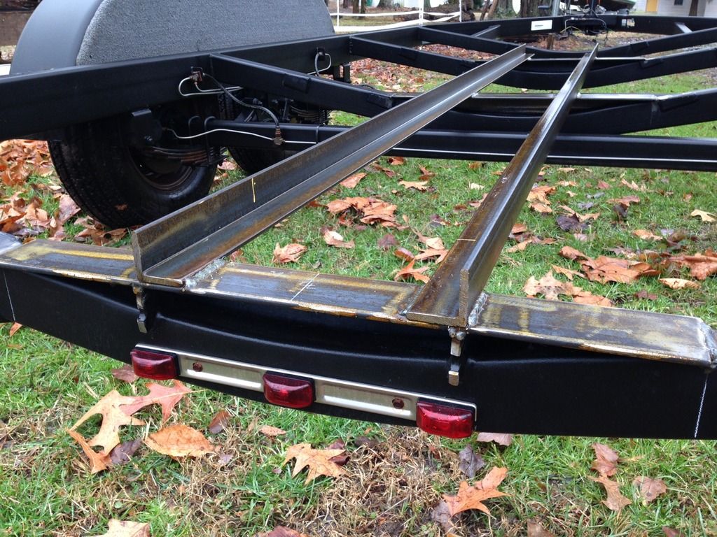
    The hardest thing about customizing an existing motorboat trailer to fit a sailboat is determining where the adjustable pads are going to land on the hull, but before that we need to figure out the foundation; i.e., keel support, center of gravity and how far above the axles the boat is going to rest.


    Here you can see that I lopped off all of the pre-existing motorboat supports and have started to build the keel support. In my case, the keel support starts with 3″x3″x3/16 angle laying over the top of the existing cross braces. This was too add strength and rigidity to the cross braces while raising the keel support 4.5″ over the axles. This was after determining that the axles had about 3″ of vertical movement before wheels started rubbing. I then laid 2″x2″x3/16″ angle over the top to connect the cross braces and to capture the keel support lumber.


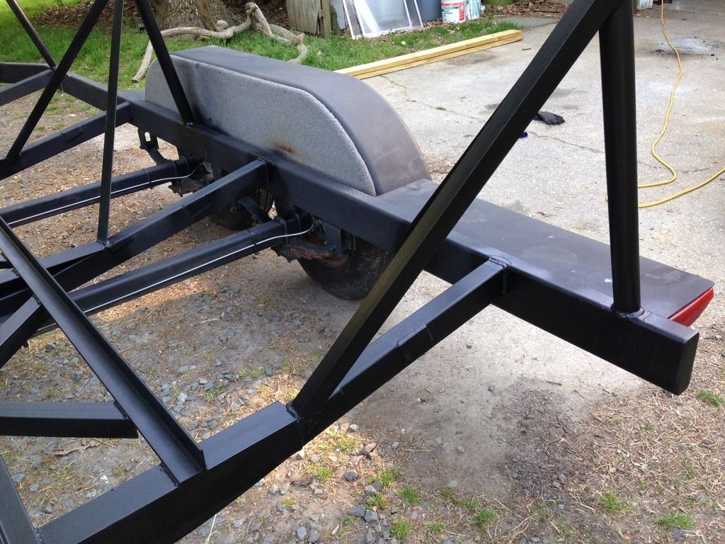
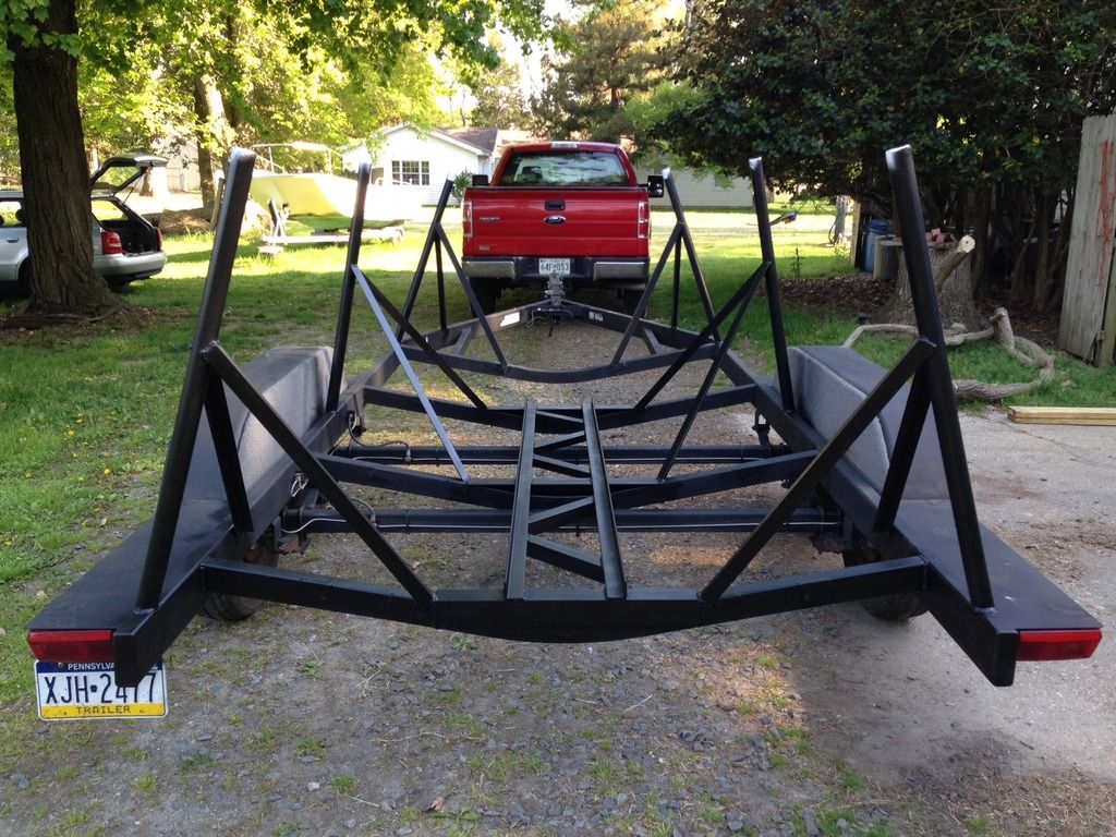
    Skipping ahead, here is the nearly complete cradle showing (Schedule 40) 1 1/2″ steel pipe used as the boat support. The pipe is taking nearly all the vertical load with 2″x2″x1/8″ angle as vertical bracing (under tension).

    As I mentioned before the hardest part was determining where to land the adjustable pads on the hull. I have to say… after looking at the original hull drawings, a sketch of a cradle in the Ariel/Commander owners’ manual, measurements taken from other Ariel trailers, and hanging an imaginary waterline off the trailer… I guessed.


    However, I did myself a favor by rough cutting the adjustable pad supports nearly 18″ longer than I needed. Then while onsite at the boat yard and with the boat in the travel-lift I hung the boat over the trailer and took measurement (X) from the bottom of the keel to the keel support. By taking X plus the height of the adjustable screw top I cut the supporting pipe down to the correct size, about 9″-15″. voila!
    A97 build images, drawings and other data:
    https://drive.google.com/drive/folde...vh?usp=sharing

  4. #259
    Join Date
    Sep 2008
    Location
    Brooksville, FL
    Posts
    720
    Matt


    Your work looks very nicely done. You are making what looks like a pretty strong trailer that should service you well.


    The only thing I noticed and it may not be the case but when I had my trailer built all of the supports were similar in length like yours look (the pipe supports that the threaded rod goes into). When we went to set the boat on the trailer we had to cut the center ones down about 8" because we could not adjust them low enough to work with the hull. So there I was with a sawzall cutting off heavy gauge square tube while the boat hull over my head on the travel lift. Hope you don't have to repeat my experience.


    Are you planning on putting a v-shaped support for the bow in the front?
    Last edited by Commander 147; 05-19-2015 at 11:54 AM.
    JERRY CARPENTER - C147
    A man can succeed at almost anything for which he has unlimited enthusiam.

  5. #260
    Join Date
    Sep 2001
    Location
    Orinda, California
    Posts
    2,311
    There is a plan for a A-C cradle in the manual. Might be helpful . . .

  6. #261
    Join Date
    Sep 2012
    Location
    Philly, PA
    Posts
    179
    Quote Originally Posted by Bill View Post
    There is a plan for a A-C cradle in the manual. Might be helpful . . .
    it was helpful! as a matter of fact, the most useful info I had to go on, besides the original hull drawings. however, a stationary cradle is a bit different than a mobile trailer. I did find that once I determined the general area where the adjustable pad was to land on the hull I could relax a little bit as the adjustable top could take up the slack....

    when i get a chance, I will make a technical drawing of the most useful dimensions in relation to the 'standard' trailer.
    Last edited by carbonsoup; 05-20-2015 at 07:55 PM.
    A97 build images, drawings and other data:
    https://drive.google.com/drive/folde...vh?usp=sharing

  7. #262
    Join Date
    Sep 2012
    Location
    Philly, PA
    Posts
    179
    Quote Originally Posted by Commander 147 View Post
    The only thing I noticed and it may not be the case but when I had my trailer built all of the supports were similar in length like yours look (the pipe supports that the threaded rod goes into). When we went to set the boat on the trailer we had to cut the center ones down about 8" because we could not adjust them low enough to work with the hull. So there I was with a sawzall cutting off heavy gauge square tube while the boat hull over my head on the travel lift. Hope you don't have to repeat my experience.


    Are you planning on putting a v-shaped support for the bow in the front?
    Yes and Yes. In post #255 you can see how the trailer was 'amended'. I did, indeed, need to cut the supports with the boat hanging over my head... it was on the only way.

    The bow support is coming soon. I will need to tow her a couple miles up the road to do the welding.
    A97 build images, drawings and other data:
    https://drive.google.com/drive/folde...vh?usp=sharing

  8. #263
    Join Date
    Sep 2012
    Location
    Philly, PA
    Posts
    179
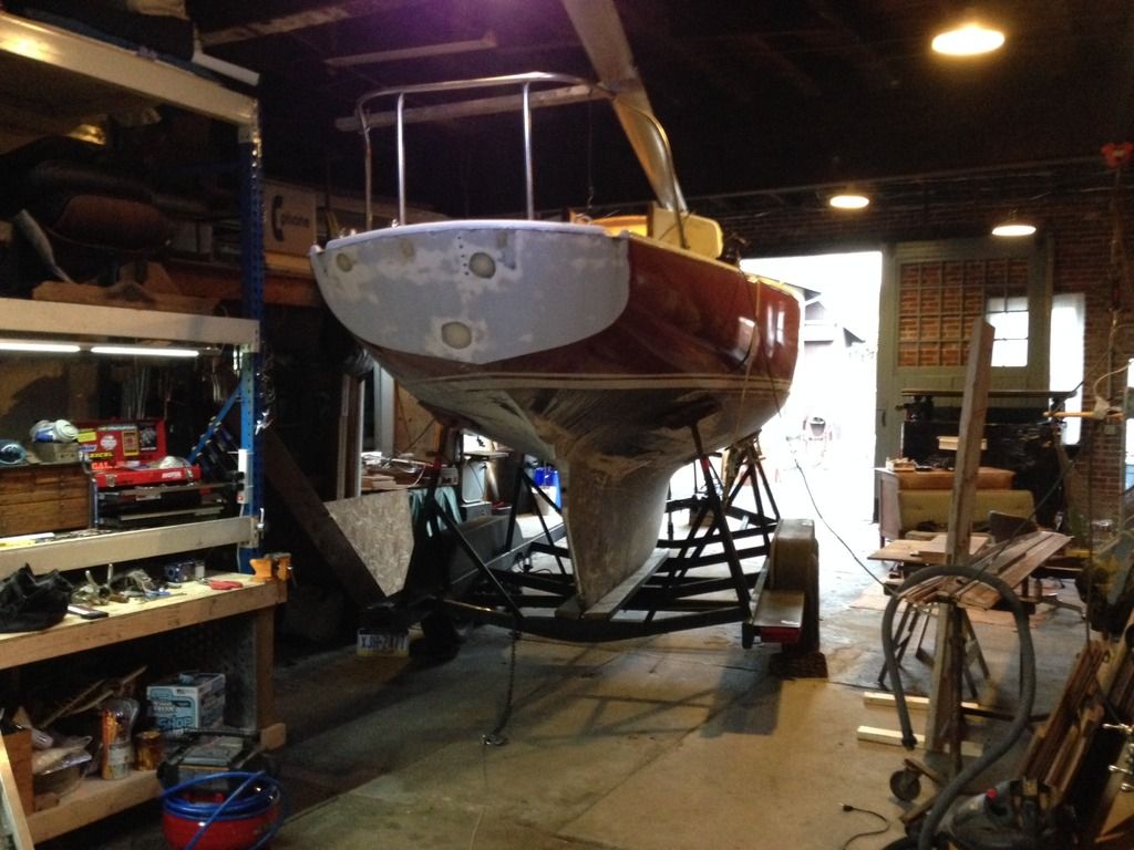
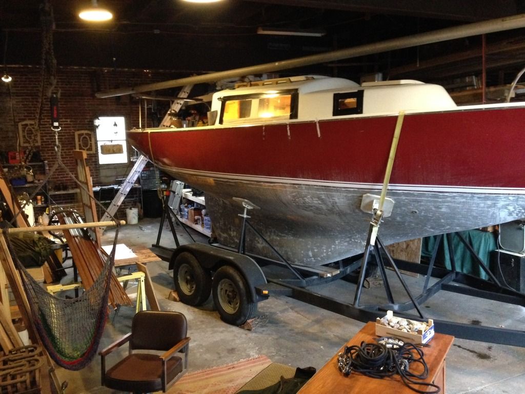
    I made it home! Finally, I can get back to work. Not sure if I will be back in the water by this coming summer or not.
    Last edited by carbonsoup; 12-08-2015 at 04:14 PM.
    A97 build images, drawings and other data:
    https://drive.google.com/drive/folde...vh?usp=sharing

  9. #264
    Join Date
    Sep 2012
    Location
    Philly, PA
    Posts
    179
    This was a an enormous project in an of it self.... just driving through Philly, down my street, backing it up the driveway and winching it the last 20ft!
    A97 build images, drawings and other data:
    https://drive.google.com/drive/folde...vh?usp=sharing

  10. #265
    Join Date
    Sep 2012
    Location
    Philly, PA
    Posts
    179
    So, my first post in a while regarding work.... now I have a dust dilemma. What have you all done to contain FRP dust in a shop? My shop and I are in a neighborhood with people living very close by, I don't want to vent directly outside.

    I have a another floor above me, kind of a attic, I was thinking of putting a large dust collector system up there with a very large settling box. Any thoughts?
    A97 build images, drawings and other data:
    https://drive.google.com/drive/folde...vh?usp=sharing

  11. #266
    Join Date
    Sep 2012
    Location
    Philly, PA
    Posts
    179
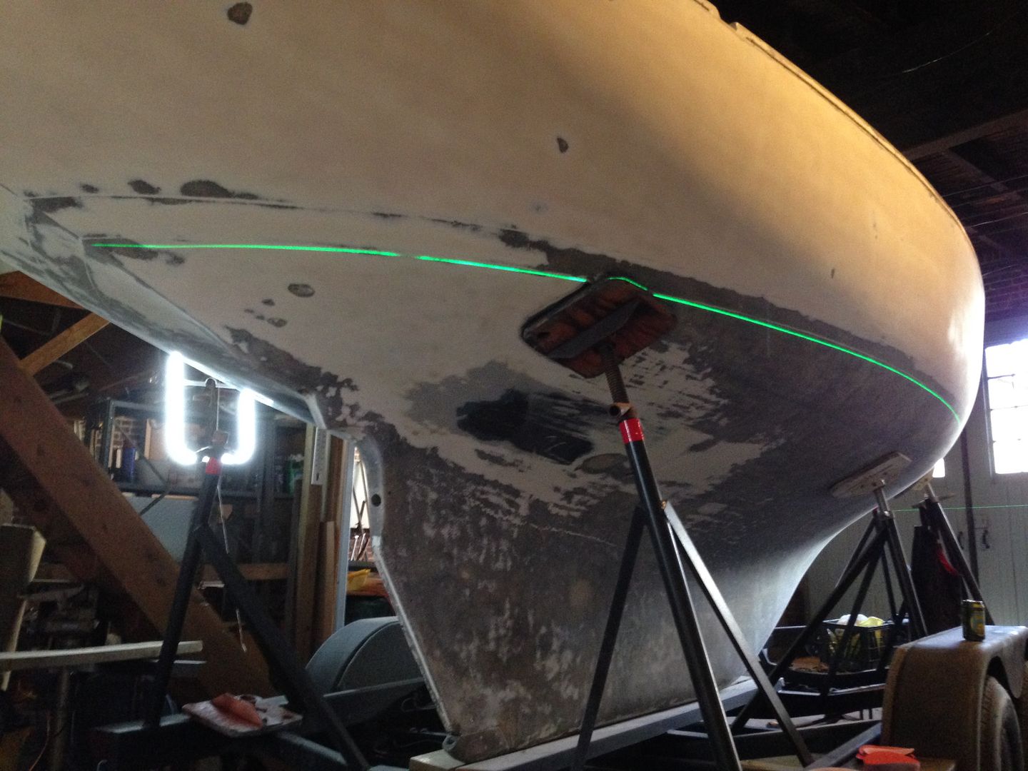
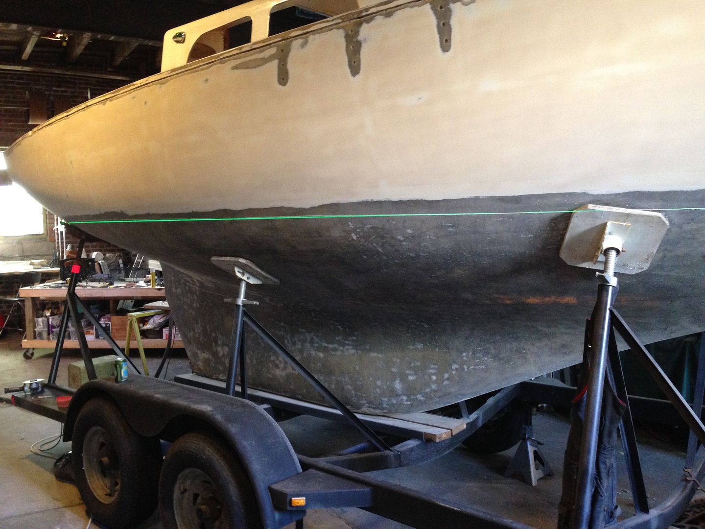
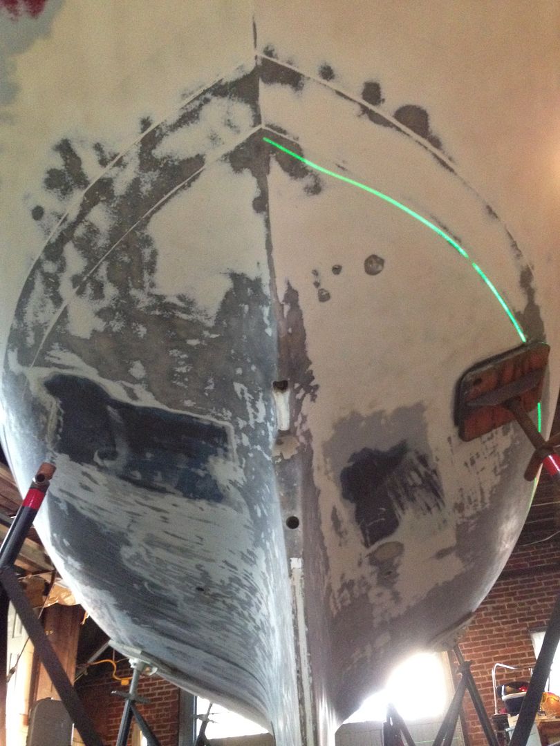
    upon water lines... now that I have ground, sanded and faired, I am thinking about the process of adding the barrier coat below the waterline and how I will lose the scribed line. So, I grabbed a laser from work to see what I was up against..


    however, after leveling the boat and lining up the laser as best I could... the molded/scribed line is either screwy or I am. Maybe a little hard to tell, but the scribed line is higher than the laser at the mid point.


    pretty neat how the scribed line actually makes a deviation from the actual waterline near the rudder. This, I know, was purposeful to create a beautiful waterline. But the above picture... im not sure.


    Anyway, when I barrier coat the raw fiberglass I am going to lose the waterline mark. Is it weird that I want to use the "string & batter board" method? As done by Tim Lackey and Louis Sauzedde, instead of using a laser? Just seems like a puff of wind or a curious kitten knocking the laser is going to ruin my day, whereas a string and some tape could be edited. Either way, I will need to take measurements from the toe rail at various points.
    Last edited by carbonsoup; 09-19-2016 at 08:29 PM.
    A97 build images, drawings and other data:
    https://drive.google.com/drive/folde...vh?usp=sharing

  12. #267
    Join Date
    Sep 2012
    Location
    Philly, PA
    Posts
    179
    and thinking seriously about a bowsprit. The biggest reason is to push the COE forward to balance the boat a bit and reduce weather helm. So far, im thinking 18" or less.


    with a tow rail cap, currently mocked up in foam, and a winch (windlass?)


    The SS oval tube is just some scrap material I had lying around at work... I liked the shape.
    Last edited by carbonsoup; 09-21-2016 at 02:23 PM.
    A97 build images, drawings and other data:
    https://drive.google.com/drive/folde...vh?usp=sharing

  13. #268
    Join Date
    Apr 2015
    Location
    Chicago, IL
    Posts
    133

    Waterline Transfer and Sprit

    Looks good. Nice work space.
    • Are you going to barrier coat below the waterline and above the waterline? If so you may want to do it in two steps. One method is before you barrier coat the top transfer the waterline onto the bottom. Take a carpenters square and lay the short edge on the waterline then make a 4-5" line and reference mark exactly 10" down the long edge of the square. Do this every 6". To transfer the line back just take the square, lay it on the line and make a mark 10" up from the reference mark. Stretch some fine line tape between the marks and you have the waterline back. It is really tricky to get the right shape near the transom. You should go closer than 6" apart there. When I stretched the tape I had to find the line that looked right. I used the marks for reference. I had a committee of onlookers drinking beers that were more than happy to render opinions.
    • I like the bowsprit. I'm looking at the removable Selden model. It is super simple to install, removable and pretty affordable. I can get you deal on one if you are interested.
      http://www.seldenmast.com/files/1441.../595-261-E.pdf

    Phil

  14. #269
    Join Date
    Sep 2001
    Location
    San Rafael, CA
    Posts
    3,621

    Barrier

    You've done an amazing job removing the gelcoat from the bottom.
    Seems essential to roll on a 2-part barrier coat. Polyester frp is porus, the fibers
    need protecting.
    Barrier coat could be clear, covering every square inch of what you took off.
    Maybe a couple coats. Paint cosmetic, coatings structural.

    Then add more barrier but make it white up to the upper scribe line.
    (assume its top of the boot stripe.)
    Then use that lazer to relocate the actual waterline, especially under the stern.
    Imco, what you've removed (microns) should be put back.

    If the bottom paint ever gets stripped, it'll be good to see the white when sanding.
    Maybe a couple coats.

    When the hull gets painted, undercoat will go down to upper scribe to keep
    awlgrip out of the water. Assume you'll have an enamel boot-top.

    My late model Ariel has a thin hull below the WL. I felt OK with
    multiple epoxy coats.

    Missed it on my Ariel, but I should have used a tank coating for the barrier,
    which generally is a tougher more waterproof epoxy.

    Beautiful oval stainless! Maybe you won't need 'shrouds'/whiskers?
    Looks like you'll need a new bow stay fitting. Wonder what your solution
    will be there? Like the built up toerail, as well!!
    ~~~~~~~~~~~~~~~~~~~~~~~~~~~~~~~~~~~~~~~~~~~~~~~~~~ ~~~

    Was just talking with PaulOman at Epoxyproducts.com. Asked him what happened to the
    NSP120 tank coating I used as a barrier years ago on A-338. It has become a pauloman
    brand (something new!) called Watergard 300 one coat. It's sold as a coating for tanks
    and as a barrier coat. Loads of info on his site and the coating. It is its own primer, and
    already white. He probably told me to use the old tank coat as a barrier...

    Ask him whether you can overcoat without toothing. Recommend at least three on a full
    keel bottom!! Make sure coating is non-blush.* No professional coating will require you
    to wash cured surface before adding the next coat. That's a fact! *Later Edit: you know,
    rereading this, it occurs to me I read this coating will blush at certain times. Watch your
    humidity. If it's low in relation to temp, you won't have a problem.

    COATING THICKNESS: 1000mils = 1" Gelcoat was probably 20mils ???
    {Credit card is 30mils thick.}
    1/16" = 62.5 mils(two mm) --- 1/32" = 31.25 mils(one mm) --- 1/64" = 15.6 mils.
    Average thickness of two part 100% solids, epoxy coating, too thick to roll = 8mils ???
    (hope this is useful)
    ~~~~~~~~~~~~~~~~~~~~~~~~~~~~~~~~~~~~~~~~~~~~~~~~~~ ~~~~~
    When I was trying to figure out weights involved with various bowsprit materials,
    I started with long pole sprits that I've always found sexy. Mental picture of a pre
    fiberglass gaff cutter. But when sweating weights, ended up with a shortened sprit
    on deck -- which is possible when the sprit is rigged as a permanent part of the stay
    system. Could remove inboard weight, keep the outboard length, but move the
    'samson post' way forward. The post meaning, where you have the end of the spar
    at refusal. Understand it's an aesthetic problem as well as practical, but imco our
    boats are rather delicate when it comes to added weight out at the ends. Believe
    you will have some beautiful welding to do when you incorporate the oval tube into
    the bow stay fitting = more weight. Bobstay and any anchoring roller, chocks and
    pulpit. But it IS a champion bowsprit you got there!!!
    Last edited by ebb; 11-06-2016 at 08:44 AM.

  15. #270
    Join Date
    Sep 2012
    Location
    Philly, PA
    Posts
    179
    A quick thanksgiving update to the bowsprit. The basic idea is that the stem head fitting will be bolted down to the bow in the usual manner and the bowsprit will bolt to the top of the stem head fitting via 3, 1/2x13 bolts. I have yet to figure out the 'cranse iron' which will be welded to the end of the bowsprit to attach the shrouds and bobstay. Since the bowsprit is bolted I can modify or replace if necessary.

    Also, near the 'sampson post' I will have a fitting to accept a removable solent stay for heavy weather. This is not going to be a cutter rig, however I want the option for a smaller sail in heavy weather. The top of solent stay would be attached near the masthead, so that I would not need to have running backstays.


    Last edited by carbonsoup; 11-27-2016 at 05:42 PM.
    A97 build images, drawings and other data:
    https://drive.google.com/drive/folde...vh?usp=sharing

+ Reply to Thread

Posting Permissions

  • You may not post new threads
  • You may not post replies
  • You may not post attachments
  • You may not edit your posts