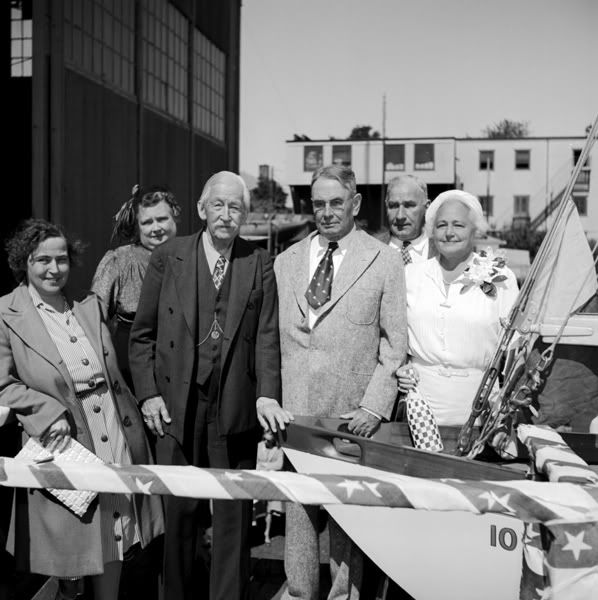
Could someone please PLEASE post pics of Little Gull before Captain Ebb sails off into the sunset?? Lots of promises, but no pics - zippo - in the last 2+ years!?? Come you guys out West, it's not like you're buried in snow or sumthin' and can't get to the boat!
 Reply With Quote

")