


3 bladed. Pics, etc. are in the threads I posted above.

3 bladed. Pics, etc. are in the threads I posted above.
Mike
Totoro (Sea Sprite 23 #626)
The prop question was decided by fate. I happened across a used 13 x 11 3 blade sailor in good condition - for 50 bucks. That is what I am goin with. I had a bit of a setback yesterday. I built a really nice engine bed. I created a framework with glass reinforced foam panel glued to a fiberglass sheet. The stringers were backed with 1/4" aluminium and I laid up 4 layers of 1708 biax over the whole thing then filled it and prepped it for an epoxy coat. All that was left was to glass it into the boat. That is when I discovered that a 21 looks just like a 12 upside down. The measurements I took from the old engine required 21" of clearance over the bed. I read 12". I designed for 16" to be on the safe side. Does anyone want a really nice engine bed? At least I know how to do it this time.
On the plus side the control panel came out really nice. I recessed it in the door behind the tiller head and built a removable box to protect the backside
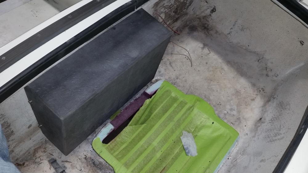
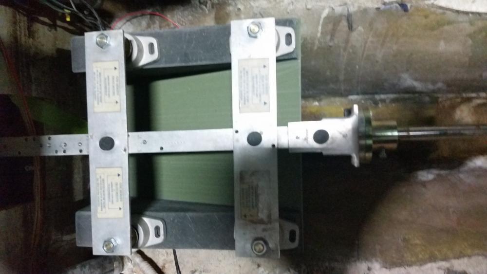
Here are some pictures of the jig in place with the now useless bed.
You know I built so many things on Destiny twice I effectively built two boats. :-( So I feel your pain. But you are getting really close and we are all cheering you on to reach the finish line. BTW I sure wish I would have had that jig when I repowered Destiny.
JERRY CARPENTER - C147
A man can succeed at almost anything for which he has unlimited enthusiam.
All of the prep work for the engine bed and the engine compartment is done. The engine had to go further forward than I originally thought to get low enough in the boat to sit below the cockpit floor. Not a problem. I cut a little into the wasted space under the companionway. The batteries will go on the starboard side. I am going to reconfigure the starboard settee to be a galley, nav station and house all of the mechanicals forward of the lazzerette. Some choices I made.
- I put in an inspection hatch on the port side that I will be able to access from the pt lazzerette.
- I am also putting in an inspection hatch in the cockpit floor. I was originally against this but I realized that if I needed to do any serious repairs the access I will get from the hatch in the cabin and the inspection port will not be enough. I will have to monitor for leakage.
- The fuel tank will sit on the shelfe above the stuffing box.
- I'm using a dripless stuffing box made by Volvo Penta. Inexpensive, easy to install and in stock. https://shop.crowleys.com/eSource3/S.../_VP%203819724
- The fuel filter, water intake throughull and the water strainer will be forward, accessible inside the cabin engine hatch
The engine goes in this afternoon.
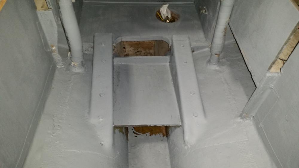
Nize work! mon, nothing like a clean bilge.
You need at least a couple ball valves on those drain exits.
Technically they seem pretty distant from any immediate access.
Ball-valves might be mounted in line on the existing stubs there,
with completely exposed on/off two-arm handles.
Wonder, since the exits are close to fore-n-aft bulkheads,
if the quarter-turn handle on the valve could be rigged so that they
could be shut off remotely. A dowel pinned to the handle
and extended along the bulkhead to the companionway
where they could be pushed to close, for instance, and pulled
to open.
Or better, if pinned to the bottom of the two-armed handle,
you would pull the dowel to close the valve,
and push it to open the valve handle in line with the hose.
That way would keep the extension 'handles' out of traffic.
just talking.....
Last edited by ebb; 03-05-2016 at 08:09 PM.
I am definitely going to install shut off valves while I have the easy access. I will be able to get to them pretty easily from the hatch in the cockpit floor and can reach them from the access door in the cabin. The question is how to affix them to the fiberglass stubs. Should I cut the stubs flush and install through hulls or epoxy a nipple to the stub. The epoxy nipple would be easier, cleaner and not to mention cheaper but the throughull would be more secure. How have other owners done this?
Well, depends I think on where you're taking the boat.
Doing it right with upgrade thru-hulls and seacocks is best I think.
Your fore-n-afts look too close to easily use the existing hole for new thru-hulls.
But maybe you can because the photo shows a pretty clean job by Pearson.
You'd be slicing and grinding off the stubs tight to the hull.
If Pearson didfn't fudge the holes thru too much, they might be opened up for
screw in thru-hulls. Assume the glass pipe was not tabbed through the hole but
is inside the hull.
But it doesn't look like you have room for seacock bases or the smaller conversion
base that allows use of ballcocks. Pictures here, don't know how to access.
I think Grocco finally came up with them, bases to allow inline ballvalves to be
use as seacocks. Good idea but a lot more plumbing connections.
If you decide to use an inline ball valve maybe it will be plastic. There are some
robust ball valves out there. But myself would have trouble trusting them.
Did finally use marilon in Littlegull.
Pearson used fiberglass tube not pipe size stuff. I don't know what you got there?
1 1/4", 1 1/2"? You could locate a couple inlines, which usually have female ends,
and just maybe you could glue them in. But then what? Male end inline ball valves
*could be connected to the fiberglass stub with a very short very stout piece of hose.
Overkill would be to securely bolt traditional seacocks to the hull. And use thru-
hulls that screw into the seacock from outside. That way everything can easily be
taken apart and replaced if ever necessary. (I've pointed out elsewhere, that if
the seacock is planted on epoxy glued backing blocks, you've using bronze bolts
to fasten it to the hull, the thru-hulls are secondary, because if you unscrew them
with the bedded seacock in place, the hole won't leak....unless the valve is open!)
Expensive. But classy and increases the value of your biscuit there!!
Are you going to insure your investment?
If your choice is bronze or marilon ball valves, you'll need room to turn them onto
threaded base or conversion base.
*McMasterCarr has some glass-filled polypropylene double union inline valves. Double
unions, if they remain waterproof, would allow easy replacement of the valve body
without disturbing anything else in the installation. www.mcmaster.com/#ball-valves/
Problem, of course, is that there always will be water in the hose... and valve.
However, there are a bunch of our boats out there still floating, probably a little
apprehensively, on Pearson's original cheap installation. Which, if you invested in
some real nice expensive underwater plastic spiral reinfirced rubber hose (Trident)
and 100% s.s. hose clamps...could always get back a little later to do it better!!
Well, cheap.. but no gizmos to clog, no valves to freeze up. Gooed argument for
simplicity. And a couple of those new plastic cone plugs in case the hose pulls off.
and a real easy to find mallot to whack em.
Last edited by ebb; 03-07-2016 at 09:50 AM.
I think I'll cut and grind them flush and install screw in throughulls and ball valves. More work but better piece of mind.
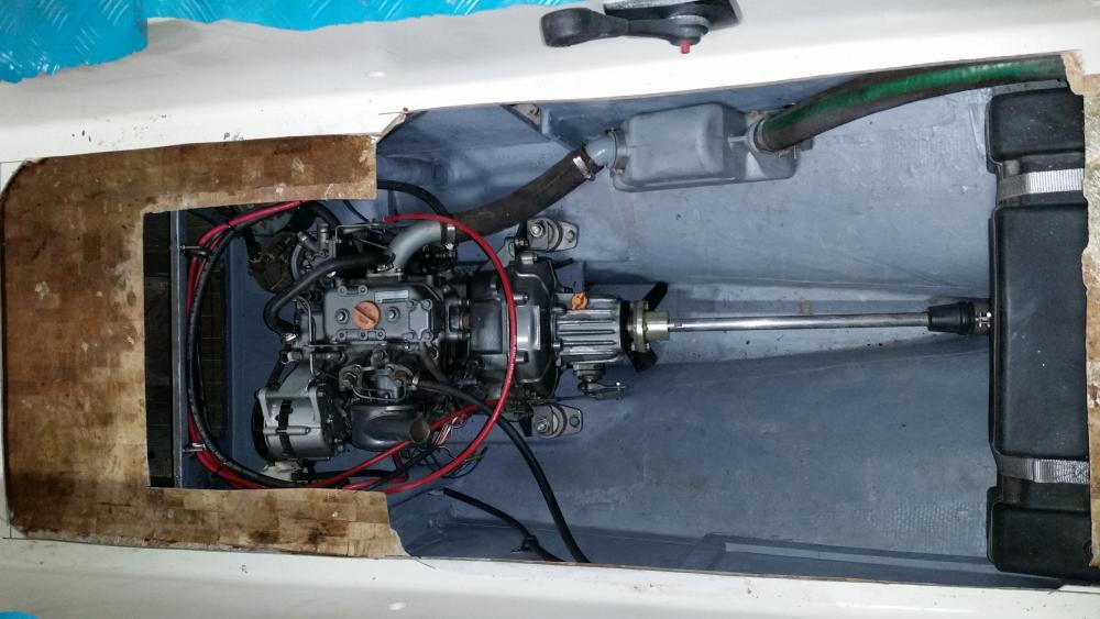
The engine is in and all the related systems are installed. I am putting the cockpit floor back together right now.
Some details on the engine choices:
Yanmar 2GM
Racor 120 A Fuel Filter
Groco ARG 75 water strainer
Volvo dripless stuffing box
Yanmar Type B panel with tack
10 gallon Tempo marine fuel tank
Teleflex single lever shifter
3 bladed bronze fixed prop with shaft zinc
The cutlass bearing is set in the stern tube and held with two set screw/Helicoil combos.
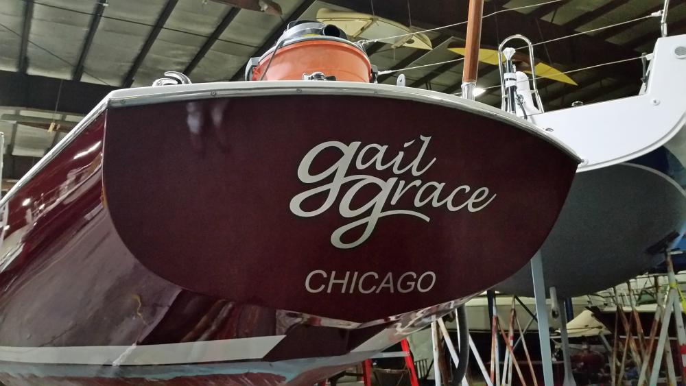
Time to get rolling on the mast and boom. Going with a tides marine mainsail track, and a new furlex furler. Oh yea - I put the new name on today.
That's what we did. The peace of mind is worth the effort. You've spared no expense elsewhere on GG so it makes perfect sense to go that route. I used 1 1/2" but 1 1/4" might have been a better fit.Originally Posted by Bisquit

My home has a keel.
Working on the rig now. I stripped all the hardware off and and modifying the masthead to accept modern exit boxes. All of the halyards will be run internally.
I welded in some aluminium bar stock into the existing sheave box opening, ground it flush and then fitted some really nice Harken sheave boxes I scavenged from a Mumm 36 rig that got on the wrong side of a semi truck. In fact, 70 - 80% of the hardware on this boat has been scavenged from totaled boats or masts. The remainder I picked up on e-bay. Getting the hardware off was a barrel of laughs. I think I broke 5 or 6 impact driver bits even though I soaked all of the fasteners with PB blaster and Kroil. I removed the external bronze main track but will reinstall it after the mast is painted and slide a Tides Marine Strong System over it. I hope to get primer on the mast, boom & spin pole tonight.
We're also going with TidesMarine.
Littlegull mast had to go with new Schaefer sailtrack.
Because the bronze track was worn at least 1/16" on one side
as if it spent its whole life holding the main on a starboard reach.
Can't remember which side.
Bad enough to worry that StrongTrack would wear, because there wasn't enough
'flat' metal for the rather soft plastic to bear on.
More like an edge that would wear and cut.
And of course, possibly become crooked over time. Or even pull off!
How the bronze track got worn on one side only is hard to fathom...
Last edited by ebb; 04-22-2016 at 05:58 AM.
Maybe she did the transpac.Mine is in good shape. I was surprised to see they used self tapping screws to build the mast (track attachment too) . I am going to rivet it back on.
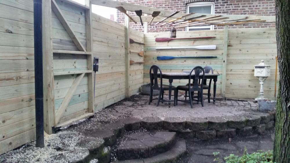
Last weekend I had to replace my fence. Put my son to work and we built this.
 Posting Permissions
 Reply With Quote