+ Reply to Thread
Page 5 of 8 FirstFirst 1 2 3 4 5 6 7 8 LastLast
Results 61 to 75 of 107

Thread: C-025 Bisquit

  1. #61
    Join Date
    Apr 2015
    Location
    Chicago, IL
    Posts
    133

    Repower Continued

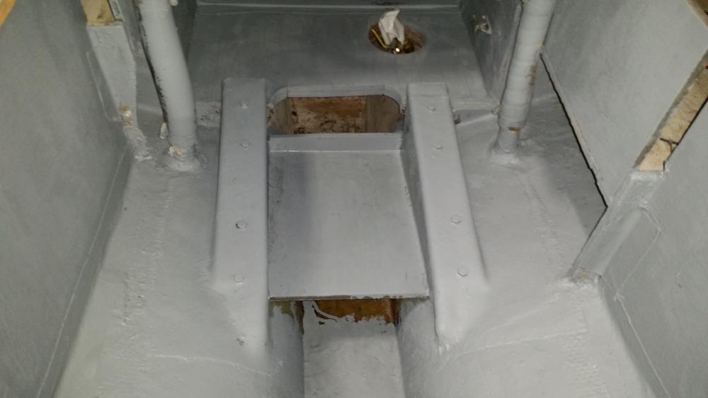
    All of the prep work for the engine bed and the engine compartment is done. The engine had to go further forward than I originally thought to get low enough in the boat to sit below the cockpit floor. Not a problem. I cut a little into the wasted space under the companionway. The batteries will go on the starboard side. I am going to reconfigure the starboard settee to be a galley, nav station and house all of the mechanicals forward of the lazzerette. Some choices I made.
    • I put in an inspection hatch on the port side that I will be able to access from the pt lazzerette.
    • I am also putting in an inspection hatch in the cockpit floor. I was originally against this but I realized that if I needed to do any serious repairs the access I will get from the hatch in the cabin and the inspection port will not be enough. I will have to monitor for leakage.
    • The fuel tank will sit on the shelfe above the stuffing box.
    • I'm using a dripless stuffing box made by Volvo Penta. Inexpensive, easy to install and in stock. https://shop.crowleys.com/eSource3/S.../_VP%203819724
    • The fuel filter, water intake throughull and the water strainer will be forward, accessible inside the cabin engine hatch

    The engine goes in this afternoon.

    Name:  2016-03-05 08.13.41.jpg
Views: 2454
Size:  45.6 KB

    Name:  2016-03-05 08.14.35.jpg
Views: 2527
Size:  41.0 KB

    Name:  2016-03-05 08.14.16.jpg
Views: 2455
Size:  40.8 KB
    Attached Images  

  2. #62
    Join Date
    Sep 2001
    Location
    San Rafael, CA
    Posts
    3,621
    Nize work! mon, nothing like a clean bilge.

    You need at least a couple ball valves on those drain exits.
    Technically they seem pretty distant from any immediate access.

    Ball-valves might be mounted in line on the existing stubs there,
    with completely exposed on/off two-arm handles.
    Wonder, since the exits are close to fore-n-aft bulkheads,
    if the quarter-turn handle on the valve could be rigged so that they
    could be shut off remotely. A dowel pinned to the handle
    and extended along the bulkhead to the companionway
    where they could be pushed to close, for instance, and pulled
    to open.
    Or better, if pinned to the bottom of the two-armed handle,
    you would pull the dowel to close the valve,
    and push it to open the valve handle in line with the hose.
    That way would keep the extension 'handles' out of traffic.

    just talking.....
    Last edited by ebb; 03-05-2016 at 08:09 PM.

  3. #63
    Join Date
    Apr 2015
    Location
    Chicago, IL
    Posts
    133

    Drain Valves

    I am definitely going to install shut off valves while I have the easy access. I will be able to get to them pretty easily from the hatch in the cockpit floor and can reach them from the access door in the cabin. The question is how to affix them to the fiberglass stubs. Should I cut the stubs flush and install through hulls or epoxy a nipple to the stub. The epoxy nipple would be easier, cleaner and not to mention cheaper but the throughull would be more secure. How have other owners done this?

  4. #64
    Join Date
    Sep 2001
    Location
    San Rafael, CA
    Posts
    3,621

    cockpit drain exits

    Well, depends I think on where you're taking the boat.

    Doing it right with upgrade thru-hulls and seacocks is best I think.

    Your fore-n-afts look too close to easily use the existing hole for new thru-hulls.
    But maybe you can because the photo shows a pretty clean job by Pearson.
    You'd be slicing and grinding off the stubs tight to the hull.
    If Pearson didfn't fudge the holes thru too much, they might be opened up for
    screw in thru-hulls. Assume the glass pipe was not tabbed through the hole but
    is inside the hull.
    But it doesn't look like you have room for seacock bases or the smaller conversion
    base that allows use of ballcocks. Pictures here, don't know how to access.
    I think Grocco finally came up with them, bases to allow inline ballvalves to be
    use as seacocks. Good idea but a lot more plumbing connections.

    If you decide to use an inline ball valve maybe it will be plastic. There are some
    robust ball valves out there. But myself would have trouble trusting them.

    Did finally use marilon in Littlegull.

    Pearson used fiberglass tube not pipe size stuff. I don't know what you got there?
    1 1/4", 1 1/2"? You could locate a couple inlines, which usually have female ends,
    and just maybe you could glue them in. But then what? Male end inline ball valves
    *could be connected to the fiberglass stub with a very short very stout piece of hose.

    Overkill would be to securely bolt traditional seacocks to the hull. And use thru-
    hulls that screw into the seacock from outside. That way everything can easily be
    taken apart and replaced if ever necessary. (I've pointed out elsewhere, that if
    the seacock is planted on epoxy glued backing blocks, you've using bronze bolts
    to fasten it to the hull, the thru-hulls are secondary, because if you unscrew them
    with the bedded seacock in place, the hole won't leak....unless the valve is open!)
    Expensive. But classy and increases the value of your biscuit there!!

    Are you going to insure your investment?

    If your choice is bronze or marilon ball valves, you'll need room to turn them onto
    threaded base or conversion base.
    *McMasterCarr has some glass-filled polypropylene double union inline valves. Double
    unions, if they remain waterproof, would allow easy replacement of the valve body
    without disturbing anything else in the installation. www.mcmaster.com/#ball-valves/
    Problem, of course, is that there always will be water in the hose... and valve.


    However, there are a bunch of our boats out there still floating, probably a little
    apprehensively, on Pearson's original cheap installation. Which, if you invested in
    some real nice expensive underwater plastic spiral reinfirced rubber hose (Trident)
    and 100% s.s. hose clamps...could always get back a little later to do it better!!

    Well, cheap.. but no gizmos to clog, no valves to freeze up. Gooed argument for
    simplicity. And a couple of those new plastic cone plugs in case the hose pulls off.
    and a real easy to find mallot to whack em.
    Last edited by ebb; 03-07-2016 at 09:50 AM.

  5. #65
    Join Date
    Apr 2015
    Location
    Chicago, IL
    Posts
    133
    I think I'll cut and grind them flush and install screw in throughulls and ball valves. More work but better piece of mind.

  6. #66
    Join Date
    Apr 2015
    Location
    Chicago, IL
    Posts
    133

    Repower Progress

    The engine is in and all the related systems are installed. I am putting the cockpit floor back together right now.

    Some details on the engine choices:
    Yanmar 2GM
    Racor 120 A Fuel Filter
    Groco ARG 75 water strainer
    Volvo dripless stuffing box
    Yanmar Type B panel with tack
    10 gallon Tempo marine fuel tank
    Teleflex single lever shifter
    3 bladed bronze fixed prop with shaft zinc
    The cutlass bearing is set in the stern tube and held with two set screw/Helicoil combos.


    Name:  2016-03-15 17.53.02.jpg
Views: 2463
Size:  77.3 KB

    Name:  2016-03-15 17.52.33.jpg
Views: 2597
Size:  75.5 KB

    Name:  2016-03-15 17.54.39.jpg
Views: 2300
Size:  89.1 KB

    Name:  2016-03-16 20.26.21.jpg
Views: 2293
Size:  50.4 KB

    Time to get rolling on the mast and boom. Going with a tides marine mainsail track, and a new furlex furler. Oh yea - I put the new name on today.

    Name:  2016-03-19 11.46.40.jpg
Views: 2324
Size:  76.9 KB

  7. #67
    Join Date
    Sep 2001
    Location
    Northern MN
    Posts
    1,100
    Quote Originally Posted by Bisquit View Post
    I think I'll cut and grind them flush and install screw in throughulls and ball valves. More work but better piece of mind.
    That's what we did. The peace of mind is worth the effort. You've spared no expense elsewhere on GG so it makes perfect sense to go that route. I used 1 1/2" but 1 1/4" might have been a better fit.
    My home has a keel.

  8. #68
    Join Date
    Apr 2015
    Location
    Chicago, IL
    Posts
    133

    Rig Work

    Working on the rig now. I stripped all the hardware off and and modifying the masthead to accept modern exit boxes. All of the halyards will be run internally.

    Name:  2016-04-19 11.50.10.jpg
Views: 2210
Size:  62.6 KB

    Name:  2016-04-20 17.05.10.jpg
Views: 2168
Size:  46.2 KB

    Name:  2016-04-19 11.50.26.jpg
Views: 2132
Size:  64.2 KB

    I welded in some aluminium bar stock into the existing sheave box opening, ground it flush and then fitted some really nice Harken sheave boxes I scavenged from a Mumm 36 rig that got on the wrong side of a semi truck. In fact, 70 - 80% of the hardware on this boat has been scavenged from totaled boats or masts. The remainder I picked up on e-bay. Getting the hardware off was a barrel of laughs. I think I broke 5 or 6 impact driver bits even though I soaked all of the fasteners with PB blaster and Kroil. I removed the external bronze main track but will reinstall it after the mast is painted and slide a Tides Marine Strong System over it. I hope to get primer on the mast, boom & spin pole tonight.

  9. #69
    Join Date
    Sep 2001
    Location
    San Rafael, CA
    Posts
    3,621

    GG looking great!

    We're also going with TidesMarine.

    Littlegull mast had to go with new Schaefer sailtrack.

    Because the bronze track was worn at least 1/16" on one side

    as if it spent its whole life holding the main on a starboard reach.

    Can't remember which side.


    Bad enough to worry that StrongTrack would wear, because there wasn't enough

    'flat' metal for the rather soft plastic to bear on.

    More like an edge that would wear and cut.

    And of course, possibly become crooked over time. Or even pull off!


    How the bronze track got worn on one side only is hard to fathom...
    Last edited by ebb; 04-22-2016 at 05:58 AM.

  10. #70
    Join Date
    Apr 2015
    Location
    Chicago, IL
    Posts
    133

    Track wear on one side

    Maybe she did the transpac. Mine is in good shape. I was surprised to see they used self tapping screws to build the mast (track attachment too) . I am going to rivet it back on.

  11. #71
    Join Date
    Apr 2015
    Location
    Chicago, IL
    Posts
    133

    Break from the boat

    Last weekend I had to replace my fence. Put my son to work and we built this.

    Name:  2016-05-01 18.18.01.jpg
Views: 2204
Size:  97.3 KB

    Name:  2016-05-01 18.19.50.jpg
Views: 2215
Size:  136.0 KB

    Name:  2016-05-01 18.18.12.jpg
Views: 2065
Size:  107.2 KB

    Name:  2016-05-01 18.18.28.jpg
Views: 2149
Size:  94.1 KB

  12. #72
    Join Date
    Apr 2015
    Location
    Chicago, IL
    Posts
    133

    Getting Close

    The boat is outside and staged for stepping and launch. I stripped the bottom but need to repair a crack in the keel before I barrier coat and bottom paint her I'm going to miss my self imposed America's Cup race deadline this weekend. I would be able to watch from my mooring but will have to watch from another boat. I'm going to step her tomorrow. I also hacked together an interior for this season - big plans for the interior next winter.

    Name:  2016-06-07 14.43.41.jpg
Views: 2066
Size:  70.0 KB

    Name:  2016-06-05 16.23.46.jpg
Views: 2135
Size:  53.7 KB

    Name:  2016-06-07 14.45.27.jpg
Views: 2101
Size:  112.6 KB
    Name:  2016-06-07 14.44.14.jpg
Views: 2205
Size:  77.7 KB

  13. #73
    Join Date
    Apr 2015
    Location
    Chicago, IL
    Posts
    133

    Gail Grace in her New Home

    Yesterday I took the Gail Grace for a shakedown cruise from the boatyard to her new home in Monroe Harbor in downtown Chicago. Light air downwind run so we popped the chute only to discover it had a Michigan State Spartan S logo. Might have to do something about that. Still have a long punch list but it will far more pleasant to work on it while she is on the can.

    Name:  IMG_3224.jpg
Views: 2024
Size:  92.0 KB

    Name:  IMG_3208.jpg
Views: 2125
Size:  79.9 KB

    Name:  IMG_3256.jpg
Views: 2113
Size:  88.1 KB

  14. #74
    Join Date
    Apr 2007
    Location
    Grand Haven / Muskegon, Michigan
    Posts
    612
    Wow! She looks outstanding. Quite a transformation from a year ago http://www.pearsonariel.org/discussi...7086#post27086 Cheers!

  15. #75
    Join Date
    Apr 2015
    Location
    Chicago, IL
    Posts
    133

    New Tiller

    I had a fairly interesting afternoon on our boat a couple of weeks ago. My son and I went out for a sail - beautiful weather, sunny, 15 - 20 knots breeze out of the west so no seas off of Chicago - a great day. On our way back into the harbor the engine died. I have been chasing a nagging air leak in the new diesel installation. I have had an intermittent problem with this since launch. I believe I have it fixed now. No big deal, We'll just sail her back to the can. Some concentration and care are required as the north end of Monroe Harbor is a fairly dense mooring field. Additionally, when the breeze is out of the west it swirls and shifts quite a bit as it channels through the tall office buildings that make up Chicago's skyline. We were coming into the can a little hot so I dropped the main just under a boat length from our mooring figuring we would easily coast right to it. Just then the wind puffed up and shifted right on our bow -- stopping us dead in our tracks. OK -- I'll just scull her the last 15 ft to the can. I started to work the tiller. I had to pump pretty hard because of the breeze -- then the tiller broke at the tiller bracket. This is about the time I remembered the old adage that a disaster is rarely the result of one mishap but rather the culmination of a series of mishaps and bad decisions. I scavenged the tiller from an abandoned boat and did a few repairs before I varnished it up and put it to work on the Gail Grace. I figured it would last the season and I would build one after I had enough time with the boat to know exactly what shape would work best. I figured wrong. I grabbed the bracket and turned the boat letting the wind take us. We were able to grab an empty can a little further down the harbor. There we bled the diesel, got the engine started and limped back to our can before the owners of the mooring we pirated came in from their sail. That night I cut up a straight tiller from an old piece of poplar I had in my basement. Just a temporary fix till I could make a proper tiller.
    This weekend I made the proper tiller. First I took some measurements, then I made a few profile templates from 3/16" luan ply. I brought those down to the boat and decided on a profile. Back in the shop I cut some True Mahogany and White Oak strips, made up a form by screwing 2 x 2s to a piece of plywood, then I covered the whole thing with shrink wrap tape. I slathered the strips with epoxy, sandwiched them in a couple of fiberglass battens then clamped them to the jig slowly drawing each clamp a few turns at a time. Yesterday morning I popped the laminate out of the jig, ran it through the table saw, the planer, the router and spent a little time with the sander. I am pretty happy with the result and it should be super strong, give me maximum room in the cockpit and enough leverage to easily steer in heavy weather.
    Attached Images          
    Last edited by Bisquit; 09-26-2016 at 06:50 AM.

+ Reply to Thread

Posting Permissions

  • You may not post new threads
  • You may not post replies
  • You may not post attachments
  • You may not edit your posts