+ Reply to Thread
Page 12 of 20 FirstFirst 1 2 3 4 5 6 7 8 9 10 11 12 13 14 15 16 17 18 19 20 LastLast
Results 166 to 180 of 422

Thread: Commander 147

Hybrid View

  1. #1
    Join Date
    Sep 2001
    Location
    San Rafael, CA
    Posts
    3,621

    rudder shape

    A place to check is a Cape Dory site.
    Might say that Alberg designed little ships with the smell of Marblehead salt water in his studio.
    So he would no doubt have small boat sailors in mind.

    CAPEDORY25D is imco pretty much his bringing the Ariel into the future. I believe the boat is
    from 1978. This design, a slightly more matronly version of the Ariel is nearly the same weight,
    length, and width as the Ariel.

    He designed it with the constellation style rudder. Which incidently appears in dashed lines on a lines drawing (Manual pg 144) of the Ariel.
    Document is not signed - it is dated: November 1961 - from the same Carl A. Alberg studio in Marblehead....... 1961 ! !

    I don't have any CapeDory lines to do closeup comparisons.
    But Alberg, 15 years later, did draw his day sailor/racer CAPEDORY TYPHOON with the round trailing edge of wooden boat heritage. I don't know if the daysailor's rudder is the more simple plank design.
    Notable, but only looking at computer images, is that the bottom of the Typhoon rudder seems to be drawn below the keel line. Not rounded up as quickly as the A/C. The rounded shapes are different.

    It is often pointed out that when you ground on mud or sand with a keelhung rudder, that an ear shape
    design to the appendage might be more likely to be freed to help manuever the vessel - and protect the blade.
    So depending on your cruising ground, you can choose your rudder if, as Ben says, there is no discernable difference in speed or maneuverablity.


    It evidently did make a difference to Olin on the 1964 Constellation (Sparkman/Stephens) when they first raced it out there.*
    Given the dates, I'm assuming Olin called up Carl and asked him what he would do to get a 12meter to go faster.
    By the numbers, it's obvious we must credit Carl with the invention of the constellation rudder. But of course!

    While the rounded rudder looks like a dragger on the '70's CapeDory Typhoon, it looks like the straight bottom rudders on family CapeDories are canted UP slightly form the line of the keel bottom. The trailing corner shows no rounding on CD's, while the dashed Ariel has considerable.

    There is a lot of airfoil (lift) designing and experimentation lavished on modern rudders.
    I haven't visited CapeDory sites much - but I would assume the '70's rudders are a fiberglass composite of some sort and are foiled.

    I'm persuaded that streamlining the rudder into a constellation aspect at least on paper will
    add something to the efficiency of the marvelous streamlining of the Ariel/Commander hull. Who knows how much.?
    With similar blade area the foil shaped flat bottom constellation couldn't be less speedy than its predecessor.

    I wonder, however, that the rudder surface being in effect LOWER with the constellation that
    more control over the boat going downwind is experienced?
    Arguement being that lower down there is less water turmoil created by water dragging along the hull.

    Racers are minmalist. Guess that water surface is right on the designer's edge. A day racer interested in the fastest straight lines
    might calculate what the designed surface areas of the two rudders are.
    We have both to compare on the A/C - which is INCREDIBLY UNIQUE.
    An over-the-shoulder view of Alberg at his drawing table! Can SEE what he's thinking about with the two concepts.
    Use those figures as datum for calculating changes....... maybe add a little more area for good measure. Can always grind it off.
    I'm thinking more area translates to a harder tiller.

    Jerry's invention is very interesting and ORIGINAL (of course!).
    And, why not? Let's see what happens, right?
    .................................................. .................................................. .................................................. ............................................
    *Constellation was a S&S 12meter Rule (39.37ft) America'sCup defender in 1964.
    TwelveMeters experienced radical design changes each time they raced, just as the America's Cup challengers today.

    The rounded rudder shape morphed into hard edge and hard cornered airfoil and never looked back!
    Last edited by ebb; 04-06-2013 at 02:50 PM.

  2. #2
    Join Date
    Nov 2009
    Location
    Brooklyn, NY
    Posts
    467
    I am all for experimentation Ebb, but I do think we should look at all innovation critically. The Constellation's rudder was designed for better helm control downwind in a 12 meter. And the straight bottom edge and crisp corners of the rudder helped reduce drag. It was also intrinsically designed with the keel to archive it's performance breakthroughs. I sort of think adding such a rudder to our boats is bending to fashion over practicality. The Cape Dory rudders were an attempt to keep the Alberg boats contemporary in an era of detached rudders and fin keels. Bet they sail windward not too different from our much older boats.

  3. #3
    Join Date
    Sep 2008
    Location
    Brooksville, FL
    Posts
    720
    Well guys unless someone can tell me why it is a bad idea I think I will probably go with my friend Tom's suggestion since it is a compromise that allows me to add a little more rudder down low like I wanted to but also keeps the bottom of the rudder out of the mud which in Florida could be a real possibility.

    Speak now or forever hold your peace since I don't want to build this thing 3 times.........twice is enough.
    JERRY CARPENTER - C147
    A man can succeed at almost anything for which he has unlimited enthusiam.

  4. #4
    Join Date
    Nov 2009
    Location
    Brooklyn, NY
    Posts
    467
    I would be alright with the revised design. Although I'd like to see closer tolerances to the hull at the top of the rudder and a tighter radius on the back edge to bottom edge curve.

    Ben

    The skipper of the Constellation in the 1964 America's Cup was Robert N. Bavier Jr. who's father Robert Sr. was the second owner of the S-Boat Tern!

    Last edited by Ariel 109; 04-06-2013 at 03:51 PM.

  5. #5
    Join Date
    Sep 2001
    Location
    San Rafael, CA
    Posts
    3,621
    Ben, Amazing find of the actual race!
    Can't argue with you, it's like how you like your coffee.
    And coffee surely was the fashionable thing once before it became cultural.

    So using the evidence at hand we find Alberg penning the yet to be fashionable un-named rudder onto the Ariel lines back in 1961, at least two or three years before it appeared on the 12meter.

    The A/C rudder of bronze and mahogany, as I see it, a holdover from good old wood boat hertitage......is a folk rudder. It is intuitive, honed and perfected over time on countless vessels by countless waterboat professionals.
    Probably count on one hand how many builders in the old days water tank tested models of a working sailboat they built for a customer.
    And have to confess my bible once was/is Chapelle's Small Sailing Craft, so at least I'm aware of your passion.

    So here we have this fashionable new rudder sitting on an Alberg drawing of an Ariel/Commander in nineteen sixty-one.
    1961, right at the cusp of Ariels and Commanders coming into existence.
    If you believe the provenance in Alberg's hand then you have to ask why the round rudder was chosen?
    I think the original A/C rudder is a masterpiece of the dying art of wooden boat building. We can argue these rudders outlast any fashionable frp/ss rudders that have appeared on countless watercraft since.
    Imco the Pearson cousins got a better deal on the traditional rudders, I wouldn't be surprised to read they were farmed out to a woodworking boat shop that had been making rudders for 50years..... you know. I think it was a dollar choice made that didn't give us the hard edged rudders that needed to be developed more scientifically. And did shortly there after.

    Can't argue that airfoil shapes to the rudder surface is fashionable.
    BUT it is more like a Darwinian mutation because the change is way more efficient at moving a shape through water.
    It appears on stand-alone rudders, and probably had to be applied to keel hung rudders, by back thinking. Since it is the slender half of a wingfoil on the end of a keel.
    And I'm certain that Alberg was aware of the changes happening in his field. Full keels and internal ballast by the time A/Cs appeared were already going out of fashion - altho it took a decade or more for the wooden-boat-translated-to-plastic way of boat design moved wholly into recreational boats for the middle class. Where I'll grant you: fashion sleight of hand and hype went arm in arm to the bank.

    Alberg's fame rested on safe, wholesome, fullkeel sailboats - and we know he was a genius and a tyrant for that style of blue water boats. The board rudder was on its way out and what the speedos found out about rudder efficiency couldn't be denied. In fact those advances were more to what Nature had already figured out since fish swam in the sea.
    Last edited by ebb; 04-08-2013 at 07:25 AM.

  6. #6
    Join Date
    Nov 2009
    Location
    Brooklyn, NY
    Posts
    467
    Here's a picture of a Sparkman and Steven rudder of the Constellation style from one of their ocean racers from the mid sixties. You can glean some interesting details!


  7. #7
    Join Date
    Sep 2001
    Location
    San Rafael, CA
    Posts
    3,621

    That starry rudder

    Pretty sharp.
    .................................................. .................................................. .................................................. ..............
    Was going to leave it at that.
    But keep coming back to looking at that amazing rudder blade.
    It's a translation, imco, right out of the test tank.
    We can see the curves on the surface, as if the foil had just been tuned by a craftsman.

    The techies did tilt the bottom up so it wouldn't crunch on the hard.

    Years ago, looking up formulas for the foil, discovered that one shape rules them all.
    One that all rudder shapers use. Or are definitely aware of. More or less.
    A foil formula would work perfectly on a rectangular blade, which they aren't hardly ever.
    So the rudder shaper is right back with his bronze & mahogany buddies......
    he has to shape by EYE. Because the 'formula' infinitely changes on an non-rectangle blade.

    Imco, getting the 12meter ready to win, designers would constantly, up to the race, be twiddling with the rudder.
    Because it is an unknown, you have to work toward perfection - which we all know is unattainable......but let's keep trying.

    Believe ledgendary surfboard shapers haven't got no stinkun formula: it's by eye. intuition, and feel.
    Stick THAT in yor blinkin computer.

    Do hold that shaping a rudder is in the realm of art.
    Do hold that Alberg designed a foil shaped underbody into the Ariel/Commander, including the leading edge bulb entry.
    So having the rudder profile as a foil is your call. It can be argued that board rudders with rounded trailing ends sailed just fine for 50 years.
    On my composite constellate there will be a conservative 0012 aft foil profile leading to a fairly narrow blunt trailing edge with hard corners, no round.
    Also will fill out the vertical profile to just inside the width of the keel. It's problematic but still the idea as to reduce drag and minimize eddys. It's also a more stable and more natural profile. One side of a board rudder is always cupped, imho.
    Will stay within the aft two thirds of the NACA airfoil ordinates. No bulge, a sort of pumped up straight line.
    google Keel hung rudders? http://www.boatdesign.net/forums/sai...ers-22016.html

    Unlikely, but if your BS1088Meranti cups at all, Cut the opposing shapes so that the cupped sides get glued together. Might be kidding but don't think so!
    .................................................. .................................................. .................................................. .................
    Art imitates Nature, and necessity is the mother of invention. Richard Franck
    Last edited by ebb; 04-15-2013 at 02:29 PM.

  8. #8
    Join Date
    Sep 2008
    Location
    Brooksville, FL
    Posts
    720

    Rudder update

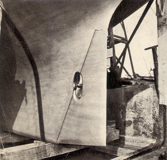
    Well, I had to buy another sheet of BS1088 plywood for the rudder because the new shape was bigger than I had material to make if from. So I decided this weekend to use the first half piece I had previously made to make a template for the new pieces when my plywood gets here. I got the top of the rudder a little too close to the bottom of the hull because I still need to wrap everything in many layers of fiberglass so I will need to cut that down some to make my template accurate.

    The bottom of this template slopes uphill at 13 degrees in addition to the lowest point being 2" above the bottom of the keel. That should keep the bottom out of the mud.

    The other thing I did this weekend was build a jig so I could install the wood rails that the motor will mount to. I made and installed the rails and now I need to glass them in. Pictures below.
    Attached Images      
    Last edited by Commander 147; 04-15-2013 at 10:51 AM.
    JERRY CARPENTER - C147
    A man can succeed at almost anything for which he has unlimited enthusiam.

  9. #9
    Join Date
    May 2008
    Location
    Excelsior, Minnesota
    Posts
    326
    Hey Jerry, sure looks good. One thing to remember when test fitting:
    You need around a half inch gap between the hull and the top of the rudder so you can lift it high enough to get it into the shoe. You can just make a notch around the shaft and turn it to one side when installing. I made this mistak when I built my first Ensign rudder and had to hack into my masterpiece at the boat yard cause I was installing and launching at the same time. I could not test fit without lifting the boat from the trailer.
    Mike
    C227

  10. #10
    Join Date
    Sep 2008
    Location
    Brooksville, FL
    Posts
    720

    Hey Mike

    HTML Code:
     One thing to remember when test fitting:
    You need around a half inch gap between the hull and the top of the rudder so you can lift it high enough to get it into the shoe.
    That is a VERY good thing to point out. And if not for shear dumb luck I could have easily missed that point. But the previous owner had a new rudder built for Destiny and they did not do a good job of allowing for that. So when I finally was able to get Destiny on a lift and remove the old rudder it did not want to come off for that very reason. That fact made me quite aware of the issue so I allowed for it this go around. Here is a picture where I was test fitting the prop location where you can see much better the notch that did not show up well in the previous picture.

    Also I found this article in Good Old Boat and used it to try and tweek the prop location. This is what I was able to work out which is as close as I could come to the ratios they recommend.
    Attached Images    
    JERRY CARPENTER - C147
    A man can succeed at almost anything for which he has unlimited enthusiam.

  11. #11
    Join Date
    Sep 2012
    Location
    Philly, PA
    Posts
    179
    looking great! your craftsmanship is a continual inspiration. I have many questions, however today I have two, maybe three, as they coincide with my own rebuild on A97.

    1. how have you calibrated the shaft alignment athwartship? Since i deleted any existence of the previous engine mount i have little to align against. The only thing is the cockpit bulkhead, a theoretical perpendicular, however the shaft does not actually exit the boat parallel to the centerline. Or does it?

    2. three blade prop for electric conversion? for regenerative efficiency? what is the spec? I was thinking of an Atomic4 prop (http://www.atomic4.com/propeller.html) seemed like a reasonable price for a three bladed prop that would fit our aperture.

    and unrelated.

    3. I sent an PM about your masthead setup. would your fabricator be interested in making another? I ask, as it might be quicker and easier than trying to get my busy fabricator to sit down and make it happen.

    ok, one more!

    4. I have spent days trying to get the Pearson Ariel cast aluminum mast base out of the bottom of the extrusion to no avail... the PO had snapped the screws (x4) off years ago so its on there. Ive heated, smacked, chisled, used penetrants... but there is just no 'purchase' to pry or lever the base cap off, any suggestions?

  12. #12
    Join Date
    Sep 2008
    Location
    Brooksville, FL
    Posts
    720
    I saw your post this morning but I am on my way out to see a customer in Orlando this morning and can't take time right now to give your questions the response they deserve. Hopefully tonight I can. In the meantime I did not get a PM from you. So you might want to try that again.
    JERRY CARPENTER - C147
    A man can succeed at almost anything for which he has unlimited enthusiam.

  13. #13
    Join Date
    Sep 2008
    Location
    Brooksville, FL
    Posts
    720
    Carbonsoup

    In response to your question #1.. I would not use a bulkhead installed in a Pearson boat from our era to align anything. I can tell you none of the bulkheads in my boat were perpendicular to the fore and aft centerline. They were as set buy the TLAR (that looks about right) method. And yes the shaft should be dead on the boats centerline. The way you have redone your boats interior would make it impossible to use the method I did (which is to streatch a mason's string tightly from the point of the bow to the point where the shaft exits the boat) to align the shaft on the centerline but you could probably figure out a suitable alternate method like determining the centerline of your cabin bulkhead and stretching a string line from there to the exit point of the shaft.

    Question #2.. The reason I went with the prop I did (which is an 11 x 11) reasons. First I determined the diameter that would best fit the aperature in the keel and rudder based on the ratios from that Good Old boat article I posted previously. Then I worked closely with Scott McMillian from Electric Yacht to determine what would be the best pitch for the 2:1 reduction we were using for my electric motor and the output power it developed at the shaft.

    As far as regeneration I'm not holding a lot of hope for that even though my system will work that way. And the 3-blade prop will do a better job for regeneration than a 2-blade one would do. But from people that have done systems like this they don't feel they get a lot of benefit from it.

    Question #3.. Yes the fabricator I used would be happy to make another mast head assembly. Are you planning on following Mike's advise (C227) about lowering the forward sheeve on the assembly? If so it would take a bit of time to rework the drawing. I can help you get it ordered with the fabricator I used. Shoot me an e-mail so we can discuss. My e-mail address is gocarpen at tampabay dot rr dot com.

    Question #4.. When I was removing my mast base I accidentally snapped off a couple of the screws also. You will never get the base off if you don't completely drill out those screws. When I did it I ended up with buggered up holes in the bottom of the mast that I had a welder plug at the same time he plugged all of the other no longer needed holes in the mast. Once I got the broken screws out completely the base came off pretty easily. Before that there was NO moving it.

    Hope this helps.
    JERRY CARPENTER - C147
    A man can succeed at almost anything for which he has unlimited enthusiam.

  14. #14
    Join Date
    Sep 2008
    Location
    Brooksville, FL
    Posts
    720

    Starting to look like an inboard drive :-)

    This afternoon I got the motor shaft lined up with the prop shaft and connected the two. Everything appears to be where it belongs with the prop and everything else so now I can glass in the shaft log.
    Attached Images  
    JERRY CARPENTER - C147
    A man can succeed at almost anything for which he has unlimited enthusiam.

  15. #15
    Join Date
    Sep 2008
    Location
    Brooksville, FL
    Posts
    720

    Ka...Ching....

    Now that I am getting near the end of the labor intensive work I am approaching the cost intensive portions of this restore. Today I will place the order for the new hardware which I have listed below with Rigging Only. I bought my standing rigging from them and they are VERY competitive in pricing and do what they say they will . Good people to work with. In addition to that $5,600.00 worth of hardware I am still looking at a $5,000.00 paint job, a $7,000.00 suite of new sails and $2,800.00 worth of batteries to power the electric inboard. And none of that includes any of the many more misc. items I will need before I finish. Sure am glad I do not intend to ever sell Destiny. And I hope the grandkids appreciate the boat they will have some day. :-)
    Attached Images      
    JERRY CARPENTER - C147
    A man can succeed at almost anything for which he has unlimited enthusiam.

+ Reply to Thread

Posting Permissions

  • You may not post new threads
  • You may not post replies
  • You may not post attachments
  • You may not edit your posts